
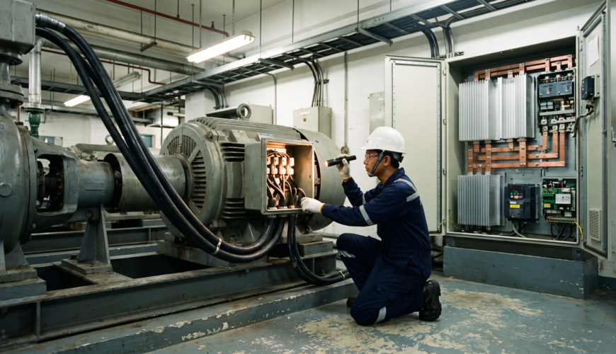
A motor that ran faultlessly for eighteen years on a direct-on-line starter comes back from a rewind, gets paired with a new variable speed drive as part of an energy upgrade, and fails inside two years. The winding shop did nothing wrong. The drive is working exactly as specified.
What changed is the shape of the voltage arriving at the motor terminals. A drive does not deliver a smooth sine wave; it delivers a rapid succession of steep-fronted voltage pulses, and insulation systems designed for mains supply were never asked to cope with that. Understanding the difference is now part of the basic groundwork for anyone specifying or repairing large industrial motors.
Why the Waveform Is the Problem
Modern drives switch using insulated gate bipolar transistors with rise times measured in tens of nanoseconds. Each switching event sends a voltage step down the motor cable, and because the cable and the motor have different surge impedances, part of that step reflects back at the motor terminals. The reflected and incident waves add together.
The practical consequence is that peak voltage at the motor terminals can approach twice the drive’s direct current bus voltage, and on long cable runs it can exceed that. A 400 V system can therefore present well over a kilovolt in repeated pulses to a winding that a nameplate would describe as a low voltage machine. Cable length is the dominant variable, and the effect becomes pronounced on runs beyond a few tens of metres.
What Fails First
The turn-to-turn insulation between adjacent conductors in the first coil takes the worst of it. Steep-fronted pulses do not distribute evenly along a winding; a disproportionate share of the voltage lands across the first few turns, which is why converter-related failures so often show up as a localised burn near the line end instead of a general breakdown.
Where the pulse stress is high enough to initiate partial discharge inside small voids in the insulation, degradation becomes progressive. Each discharge erodes a little organic material, and standard enamels have no meaningful resistance to that process. This is a genuine addition to the familiar causes of electric motor winding failure, and it behaves differently because the damage accumulates invisibly until the margin is gone. Our motor and generator services team sees the pattern regularly on machines converted to drive operation late in their working lives.
Bearings deserve a mention alongside the winding. Common-mode voltage imposed by the drive can drive current through the bearing races via the lubricant film, producing fluting and premature failure, which is why shaft earthing arrangements and insulated bearings appear so often in converter-fed specifications.
How the Standards Split the Problem
International practice divides converter-fed insulation systems into two categories. Type I systems are expected to operate without any partial discharge at all, and are qualified on that basis. Type II systems are built to withstand partial discharge activity over their design life, using mica-based or otherwise discharge-resistant materials, and the qualification tests for them are set out in IEC 60034-18-42, covering partial discharge resistant insulation systems for converter-fed machines.
Specifying and Repairing for Converter Duty
Getting this right begins at procurement. A motor intended for drive operation should be specified as such, with an insulation system rated for the peak voltage and rise time the installation will actually produce, taking the real cable length into account instead of assuming a short run.
Repair introduces its own decision point. When a converter-fed motor is rewound, the replacement wire and insulation system need to be at least equivalent to what was removed, and frequently the sensible move is to upgrade to a corona-resistant magnet wire and an improved slot and phase separation package. ANSI/EASA AR100-2025, the recommended practice for the repair of rotating electrical apparatus sets out the record keeping, testing, and general repair guidance that underpins this kind of work, including guidance on controlling core temperature during stripping so that interlaminar insulation is not degraded.
A few measures consistently make the difference on converter-fed installations:
- Specify or upgrade to a corona-resistant magnet wire where peak terminal voltage is high
- Keep drive-to-motor cable runs as short as the layout allows, using symmetrical screened cable
- Fit an output filter or dv/dt reactor where cable length or switching frequency pushes the stress up
- Provide a shaft earthing brush, an insulated non-drive-end bearing, or both, to manage circulating currents
- Record the drive settings alongside the motor record, so a future repair shop knows what the winding has been living with
- Re-check terminal box connections after the first weeks of running, since drive-fed circuits work terminations harder
Mitigation outside the motor helps as well. Output filters, dv/dt reactors, and sinusoidal filters all reduce the severity of the pulses reaching the winding, and shorter or properly specified symmetrical cabling reduces reflection. We regularly see installations where a modest filter would have spared an expensive winding, so the question deserves an airing before a drive is commissioned and not after the second failure.
Testing a Converter-Fed Machine
Routine insulation resistance testing remains useful, though it will not reveal turn-to-turn weakness, since the test voltage is applied to earth and not between adjacent conductors. Surge comparison testing is the measurement that does probe turn insulation, and on converter-fed machines it earns a regular place in the schedule rather than appearing only after a failure. Thermal imaging of the terminal box and drive cabinet rounds out a sensible routine, since loose terminations on drive-fed circuits are a recurring source of trouble.
Getting Ahead of the Next Upgrade
Energy efficiency programmes across Singapore industry are steadily putting drives in front of motors that spent their whole lives on fixed speed supply. Most of those conversions go perfectly well. The ones that do not tend to involve a long cable run, an older winding, and nobody asking about insulation class at the design stage.
If you are planning a drive retrofit, or you have a converter-fed motor that has failed sooner than you expected, our engineers can look at the installation as a whole and advise on what the winding will need. Get in touch with MES and we will happily talk it through with you.

Linkedin Profile 